

ERVS Single duct vav box in galvanised steel.
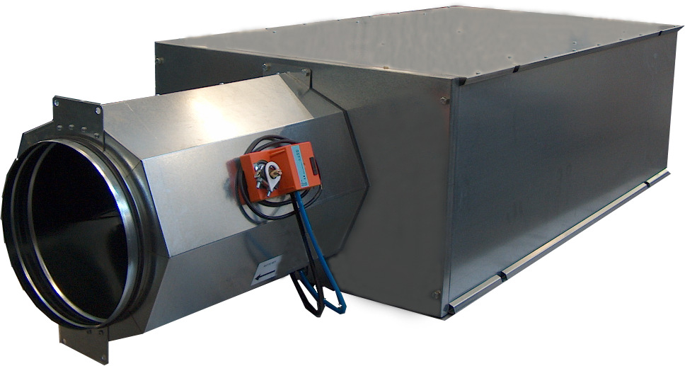
Description
These regulators are used to control and maintain the amount of air in VAV systems.
Notes
For correct pressure readings and for a flow rate tolerance of 5%, a straight duct with a length equal to 2/3 times the regulator diameter must be provided upstream. Otherwise, the air flow rate may vary between 10% and 20% from the calibrated value.
Characteristics
-Galvanised steel sheet casing;
-Dynamic Δp probe to measure and maintain the air flow rate according to the room demand;
-Galvanised steel damper with sealing gaskets;
-Operating range between 20 and 1500 Pa;
-Flow rate adjustment and control by means of a linearised motor controller;
-Self-generated and radiated noise tests according to the EN ISO 3741 Standard;
-Damper tightness test performed according to the EN 1751 Standard.
-VAV-COMPACT, AC/DC 24 V, MP-Bus, IP54 LMV-D3-M (5nm) (Standard)
On demand
-VAV-Compact, AC/DC 24 V, Bacnet MS/TP, Modbus RTU, MP-Bus, IP54 LMV-D3-MOD (5Nm)
-VAV-Compact, AC/DC 24 V, KNX (S-Mode), IP54
LMV-D3-KNX (5Nm)
Models
ERVS single casing.
ERVS-I double casing.
Accessories
Water or electric reheat coil (prices on request).
Simple casing diagram
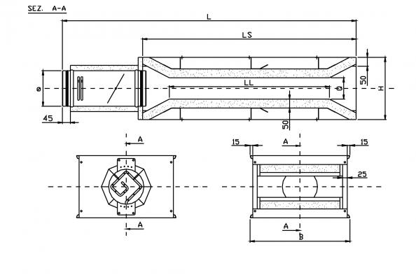
Simple casing dimensions
All dimensions are expressed in mm.
| Ø |
B |
H |
L |
Q |
LS |
LL |
| 125 | 380 | 270 | 1350 | 90 | 1000 | 800 |
| 160 | 380 | 270 | 1395 | 90 | 1000 | 800 |
| 200 | 560 | 360 | 1650 | 130 | 1200 | 900 |
| 250 | 560 | 360 | 1720 | 130 | 1200 | 900 |
| 315 | 780 | 460 | 2010 | 180 | 1400 | 1000 |
| 355 | 780 | 460 | 2065 | 180 | 1400 | 1000 |
| 400 | 980 | 510 | 2230 | 230 | 1500 | 1100 |
Double casing diagram
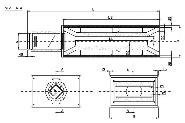
Double casing dimensions
| Ø |
B |
H |
L |
Q |
LS |
LL |
| 125 | 430 | 320 | 1350 | 90 | 1000 | 800 |
| 160 | 430 | 320 | 1395 | 90 | 1000 | 800 |
| 200 | 610 | 410 | 1650 | 130 | 1200 | 900 |
| 250 | 610 | 410 | 1720 | 130 | 1200 | 900 |
| 315 | 830 | 510 | 2010 | 180 | 1400 | 1000 |
| 355 | 830 | 510 | 2065 | 180 | 1400 | 1000 |
| 400 | 1030 | 560 | 2230 | 230 | 1500 | 1100 |
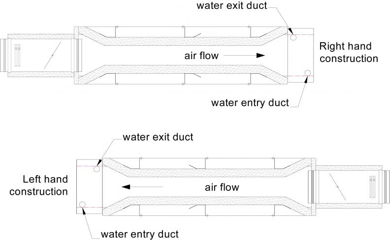
Coil for variable flow rate units
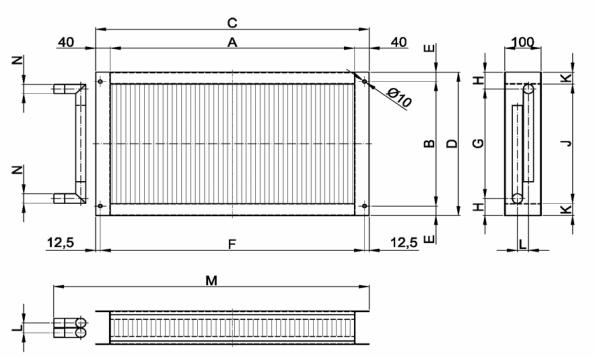
| ERVS size | Number of rows | A | B | C | D | E | F | G | H | J | K | L | M | N |
| 125 | 1 | 270 | 175 | 350 | 257 | 41 | 325 | 150 | 53,5 | 180 | 38,5 | 0 | 386 | 1/2'' |
| 125 | 2 | 270 | 175 | 350 | 257 | 41 | 325 | 150 | 53,5 | 180 | 38,5 | 26 | 386 | 1/2'' |
| 160 | 1 | 270 | 175 | 350 | 257 | 41 | 325 | 150 | 53,5 | 180 | 38,5 | 0 | 386 | 1/2'' |
| 160 | 2 | 270 | 175 | 350 | 257 | 41 | 325 | 150 | 53,5 | 180 | 38,5 | 26 | 386 | 1/2'' |
| 200 | 1 | 450 | 275 | 530 | 332 | 28,5 | 505 | 240 | 46 | 240 | 46 | 26 | 605 | 1/2'' |
| 200 | 2 | 450 | 275 | 530 | 332 | 28,5 | 505 | 240 | 46 | 240 | 46 | 26 | 605 | 1/2'' |
| 250 | 1 | 450 | 275 | 530 | 332 | 28,5 | 505 | 240 | 46 | 240 | 46 | 26 | 605 | 1/2'' |
| 250 | 2 | 450 | 275 | 530 | 332 | 28,5 | 505 | 240 | 46 | 240 | 46 | 26 | 605 | 1/2'' |
| 315 | 1 | 670 | 375 | 750 | 432 | 28,5 | 725 | 338 | 47 | 360 | 36 | 25 | 855 | 1/2'' |
| 315 | 2 | 670 | 375 | 750 | 432 | 28,5 | 725 | 330 | 51 | 360 | 36 | 30 | 865 | 3/4'' |
| 355 | 1 | 670 | 375 | 750 | 432 | 28,5 | 725 | 338 | 47 | 360 | 36 | 25 | 855 | 1/2'' |
| 355 | 2 | 670 | 375 | 750 | 432 | 28,5 | 725 | 330 | 51 | 360 | 36 | 30 | 865 | 3/4'' |
| 400 | 1 | 870 | 425 | 950 | 482 | 28,5 | 925 | 362 | 60 | 390 | 46 | 30 | 1065 | 3/4'' |
| 400 | 2 | 870 | 425 | 950 | 482 | 28,5 | 925 | 362 | 60 | 390 | 46 | 30 | 1065 | 3/4'' |
| 500 | 1 | 870 | 525 | 950 | 600 | 37,5 | 925 | 482 | 59 | 510 | 45 | 30 | 1065 | 3/4'' |
| 500 | 2 | 870 | 525 | 950 | 600 | 37,5 | 925 | 475 | 62,5 | 510 | 45 | 38 | 1070 | 1'' |
| 630 | 1 | 1070 | 655 | 1150 | 720 | 32,5 | 1125 | 595 | 63 | 630 | 45 | 38 | 1270 | 1'' |
| 630 | 2 | 1070 | 655 | 1150 | 720 | 32,5 | 1125 | 588 | 66 | 630 | 45 | 45 | 1280 | 1 1/4'' |
Operating data and price lis
When ordering, indicate the minimum and maximum air flow rates to be programmed.
Prices and characteristics of water coils on request.
| Model | Minimum air flow rate |
Maximum air flow rate |
ERVS single casing. Control signal 2...10V |
ERVS single casing. Control signal 0...10V |
ERVS-I double casing. Control signal 2...10V |
ERVS-I double casing. Control signal 0...10V |
| mm | m3/h | m3/h | euro | euro | euro | euro |
| 125 | 53 | 445 | 829,71 | 829,71 | 1093,39 | 1093,39 |
| 160 | 87 | 725 | 841,38 | 841,38 | 1167,93 | 1167,93 |
| 200 | 138 | 1130 | 1012,46 | 1012,46 | 1457,43 | 1457,43 |
| 250 | 212 | 1770 | 1029,59 | 1029,59 | 1525,42 | 1525,42 |
| 315 | 337 | 2810 | 1266,46 | 1266,46 | 1900,45 | 1900,45 |
| 355 | 428 | 3570 | 1290,47 | 1290,47 | 1953,46 | 1953,46 |
| 400 | 543 | 4525 | 1504,64 | 1504,64 | 2293,61 | 2293,61 |

