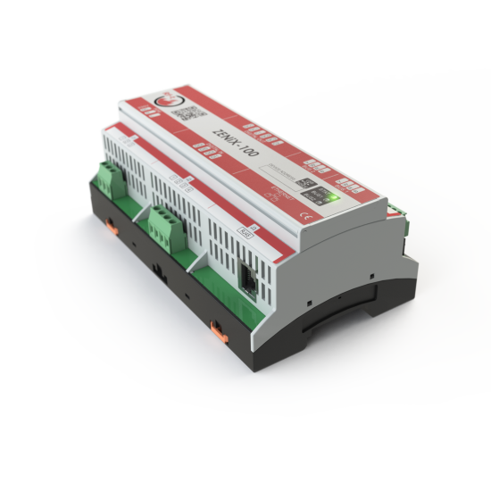
ZENiX-100 Programmable controller
Description
Smart controller for monitoring and managing fire dampers and smoke control dampers in systems. It allows integration with BMS and control up to 100 modules.
The use of the ZENiX control system together with ONE-X range products enables a bus-based control system, drastically reducing the wiring requirements in a building. This results in a significant reduction in cable and installation costs. The Webtool software, already integrated into the controller, allows the status of the dampers to be checked even during installation, leading to a considerable reduction in commissioning time.
Features
Management up to 100 field devices;
Power supply 230 V AC +/-15% – 50/60 Hz;
Power consumption 24 W - 25 VA;
Temperature range 0 … +50 °C;
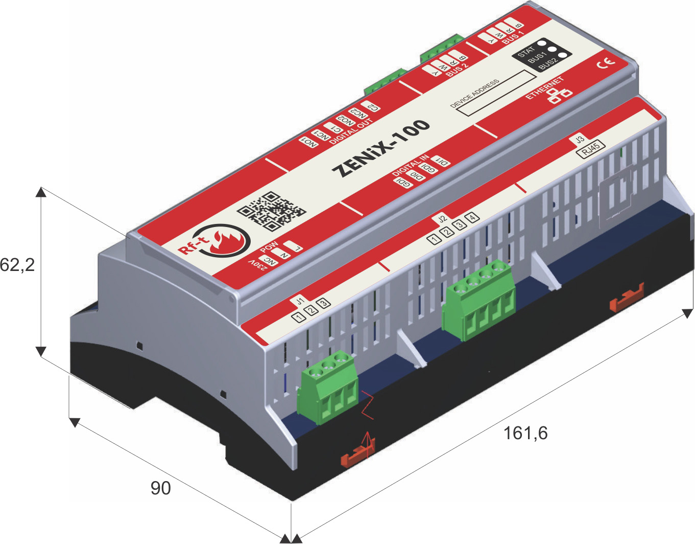
DIN rail mounting 162 mm length, dimension 162 x 90 x 62 mm;
Weight 400 g;
Through the field devices (1 FD – 2 FD) it is possible to manage 230 V or 24 V motorized fire dampers and smoke control dampers not equipped with the integrated ONE-X system;
Possibility to manage manually operated fire dampers through MFD field modules;
Integration with BMS systems via BACnet IP protocol;
2 digital inputs and 2 programmable NO/NC relay outputs;
RJ45 Ethernet port for local or remote access;
Bus communication up to 1000 m with line or ring topology;
Integrated ZENiX Webtool software for configuration, testing and scenario management;
Possibility to program complex fire scenarios;
Integrated status LEDs for bus, alarms and error indication;
According to the LVD and EMC more specifications in the technical data sheet;
Use
The ZENiX-100 can act as a gateway to a building management system (BMS) via BACnet IP, but it can also operate independently as a standalone solution.
It can be used in all applications where precise monitoring of the status of fire dampers and smoke control dampers is required.
Notes
Rft pre-commissioning can only be performed by Rft or its certified partners. For more information download the file "Terms&Conditions" on the section Documents.
Operating Data
Technical data Nominal Voltage AC 230 V ±15% 50/60 Hz Power Input 24 W (25 VA) Connections 3 terminals x max. 1.5 mm² Bus connection Bus terminal 2 x 4 x max. 1.5 mm² wire (4 colored wire) Digital input 2 x contatti puliti digitali (4 terminali, fili min. 0.5 mm² a max. 1.5 mm²) Digital Output 2 x output binari (6 terminali, fili min. 0.5 mm² a max. 1.5 mm²) – NO/NC relè (125 V AC – 60 W) Integrated Ethernet port Ethernet 10/100 Mbps with RJ45 connector Weight 400 g Bus lenght 1000 m Maximum number of field device 100
ZENiX-100 Dimensions
Lenght (m) (mm) Depht (mm) Height (mm) 161,6 90 62,2
Electrical connections
The ZENiX controller and the field modules are connected via a data bus system and communicate with each other using the BACnet protocol.
The controller supplies power to the field modules, which enables the monitoring of the various devices without the need for a direct power supply to the modules.
However, a power supply is still required for opening and closing motorised shutters; the cable cross-section must comply with system requirements and local regulations.
The bus is wired in a loop, which increases system reliability; should the loop be interrupted, the controller reroutes communications to keep the components active.
N.B. The maximum loop length for damper control is 1000 m and 100 devices.
For the connection between modules and the ZENiX controller, a 2x2x0.8 mm² KNX-type cable may be used for fire dampers, whilst for smoke dampers, a cable with fire resistance certification is required.
N.B. The specific regulations in this area must always be checked; variations in cable type may be necessary depending on the standards and applications.

The ZENiX system therefore consists of three levels:
Management: on the management side, the ZENiX receives the fire alarm signal (via a digital input) and can communicate the status of the modules in real time via the BACnet protocol;
Cabinet: this is where the ZENiX and its accessories are housed; it is already possible to supply a control panel pre-fitted with the various components, ready for installation;
Field: the term ‘field’ refers to the location where fire dampers, smoke dampers and field devices are installed;

Price list: prices available on request
Supply and installation of a controller for the monitoring and control system of fire dampers and smoke control dampers, type ZENiX-100 or equivalent, suitable for the centralized management of fire safety devices installed within the building, including fire dampers, smoke control dampers, fans and digital input and output modules. The controller shall manage a dedicated bus communication network for the connection of field devices, implemented through a four-wire cable used for both data transmission and power supply for the communication system.
The controller shall automatically recognize all connected devices through a preconfigured unique device identifier and shall ensure continuous monitoring of the operational status of all connected devices, even in case of local power loss of the field devices. The system shall allow verification and diagnostic testing of the bus wiring through integrated software tools and shall enable the identification of possible wiring errors or connection faults.
The controller shall allow integration with building management systems (BMS) via BACnet/IP communication protocol and shall enable the management of system operating logic through cause-and-effect matrices for the handling of fire alarm scenarios, normal operation, maintenance and testing conditions. The system shall also provide event logging and real-time visualization of the status of connected devices through an integrated web interface accessible via Ethernet network.
The controller shall be suitable for DIN rail installation inside an electrical cabinet, powered at 230 V AC and equipped with Ethernet connectivity for configuration, monitoring and integration with building automation systems. The connection of field devices shall be carried out through a bus wiring network using standard cable type 2 x 2 x 0.8 mm² or equivalent.
The supply shall include the controller complete with operating software, diagnostic tools, installation accessories, electrical connections, basic system configuration and any additional components required to ensure a fully operational system compliant with the project specifications.
Unit of measurement: pcs.