

ETIM Induction duct
Description
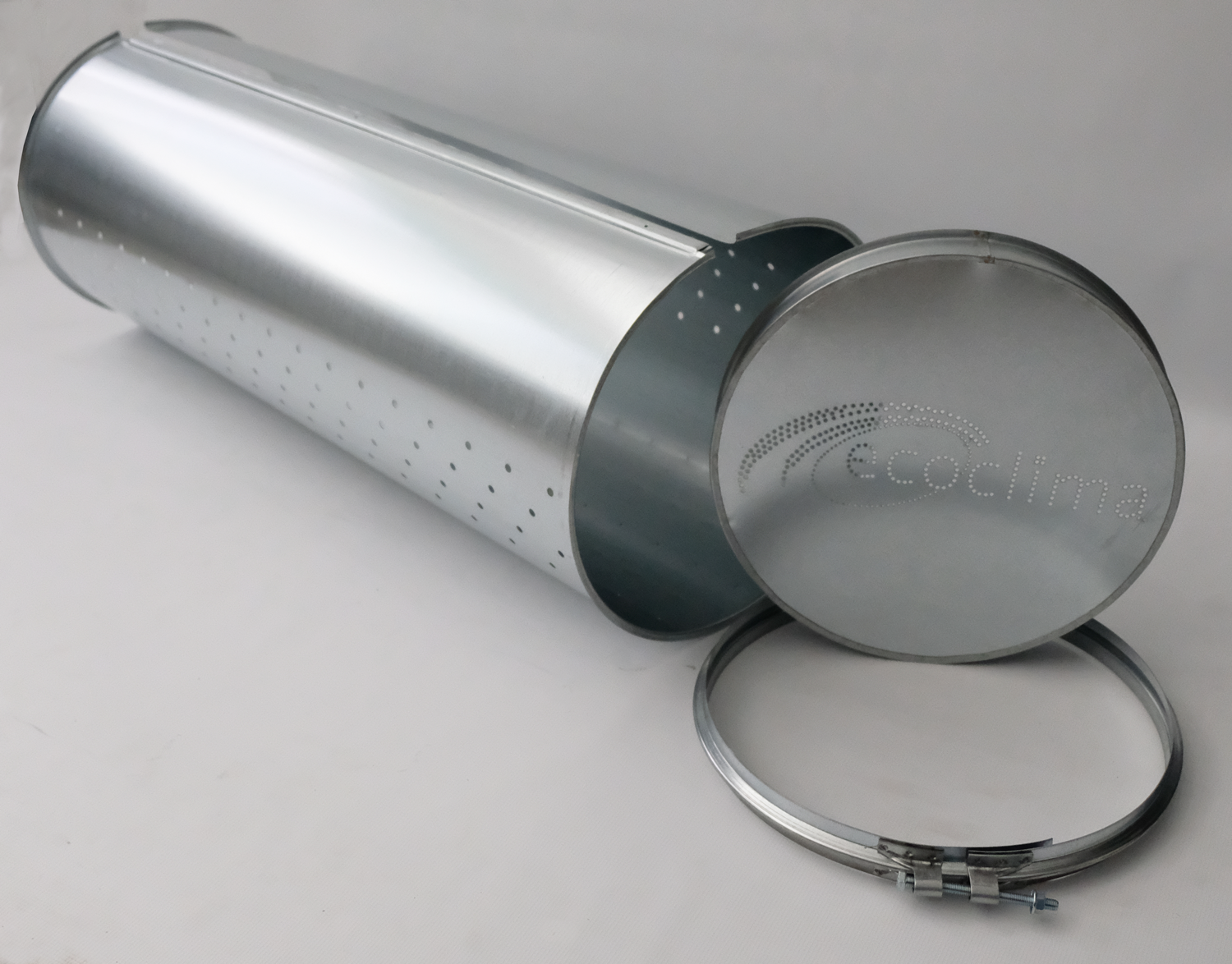
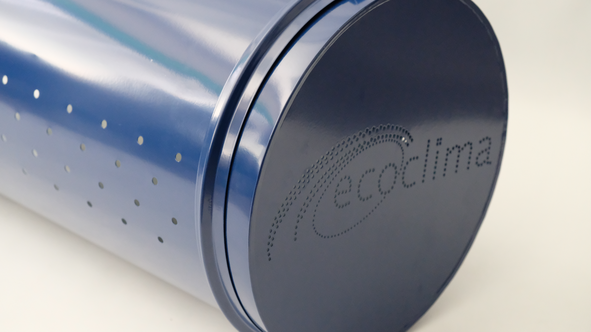
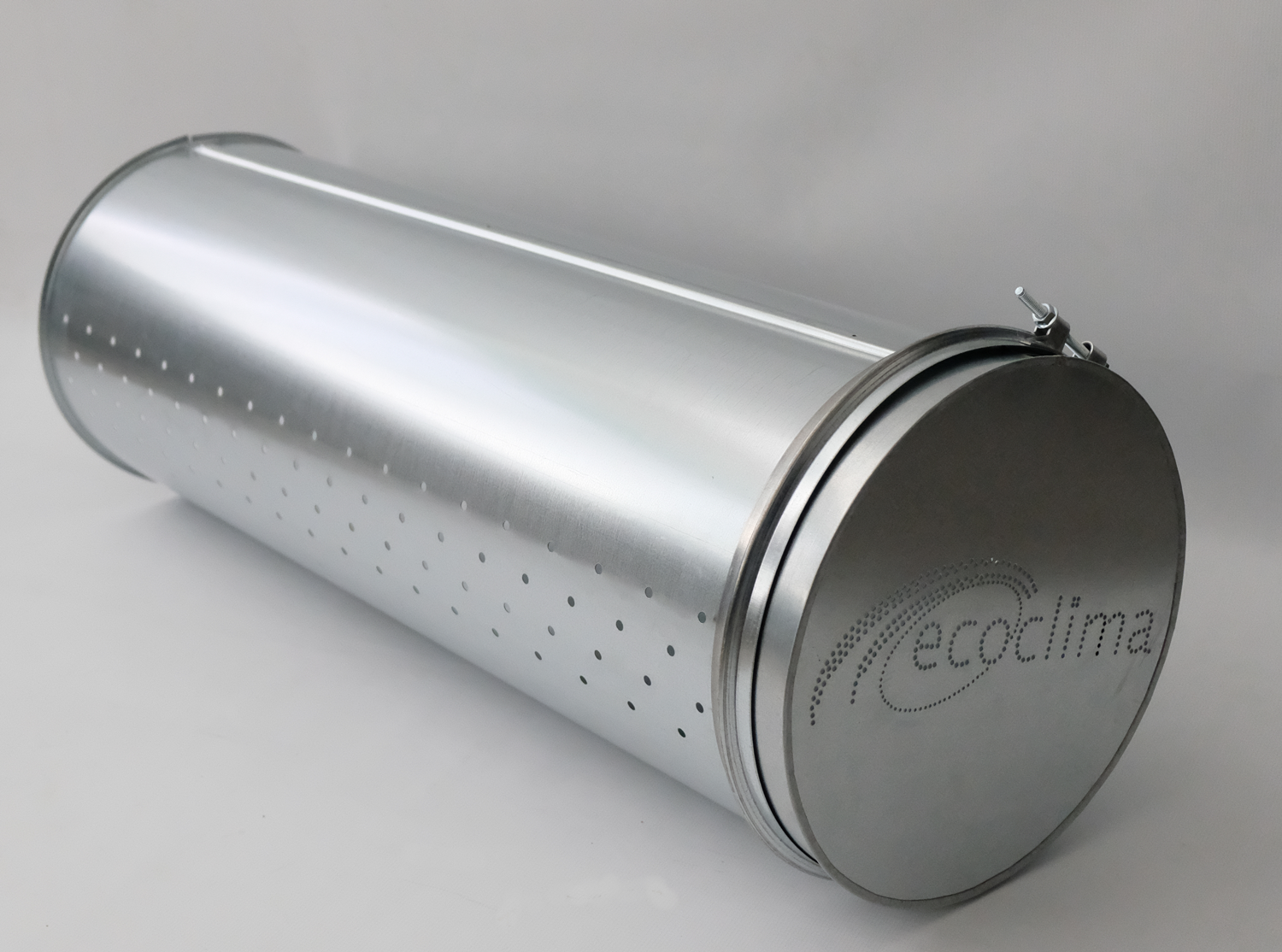
Circular section induction ducts. The perforations along the length of the duct provide a strong inductive effect, generating micro-vortices and consequently an optimal mixing of the supplied air.
Standard ducts are circular and are made in 1-meter sections with 90° coupling flanges and reinforcements at the ends. The perforations are distributed along the duct length and are created with specific diameters and geometries for each system and according to the environmental context. The large number of possible configurations makes the induction system a versatile solution for many applications in both civil and industrial settings.
Features
• Duct made of galvanized steel sheet DX51D with thicknesses:
- Ø 150–500 mm: 0.6 mm (0.8 mm on request);
- Ø 600–900 mm: 0.8 mm;
- Ø 1000–1400 mm: 1.0 mm;
• Length: 1 meter;
• Coupling with 90° flanges and reinforcement;
• Joints using omega clamps;
• Installation height:
- 2.5 m to 3.5 m (SYSTEM A)
- 3.5 m to 10 m (SYSTEM B)
- 9 m to 18 m (SYSTEM C)
On request
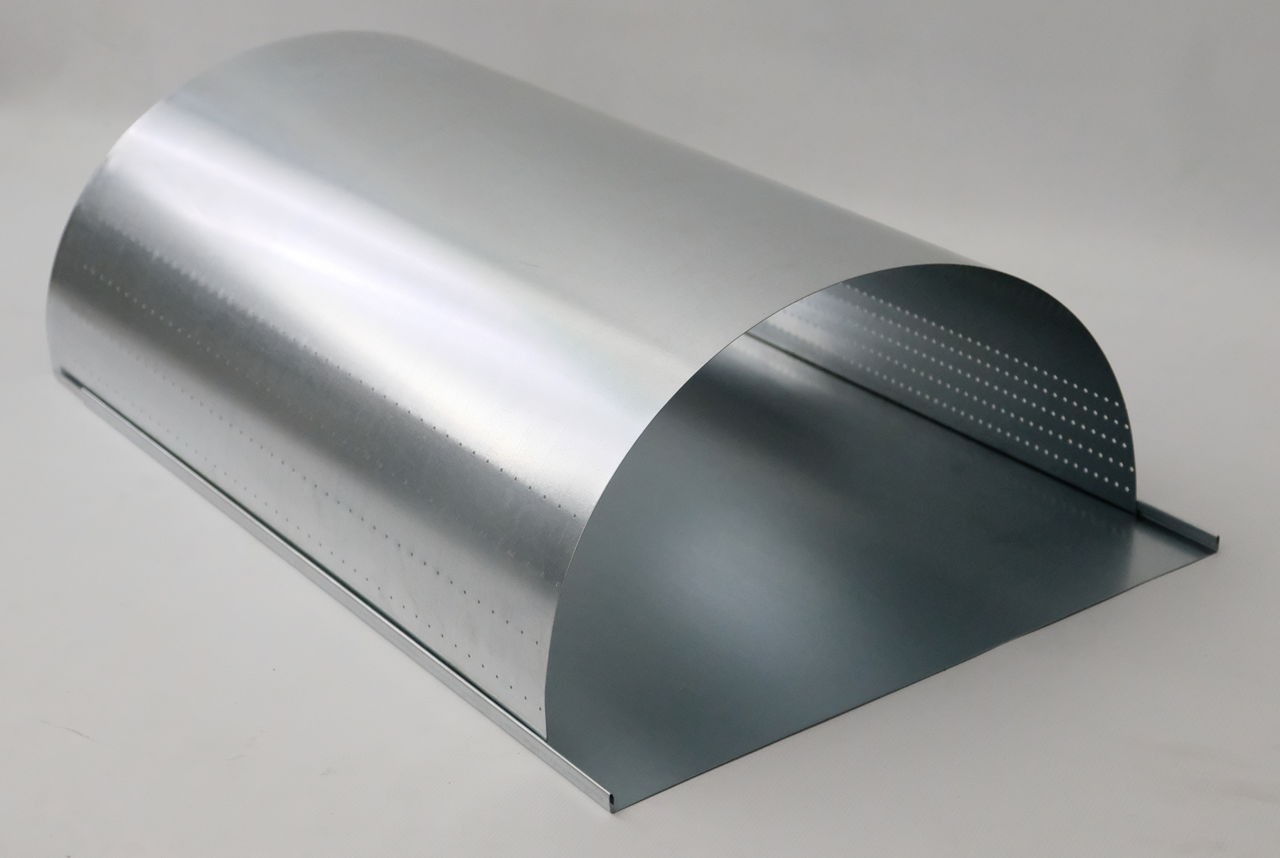
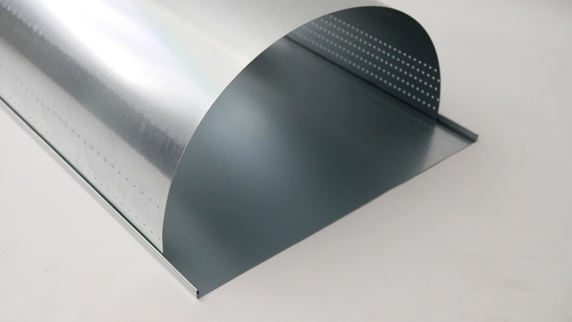
• ETIM-D version: semi-circular ducts with reduced transport costs, connected by interlocking modules;
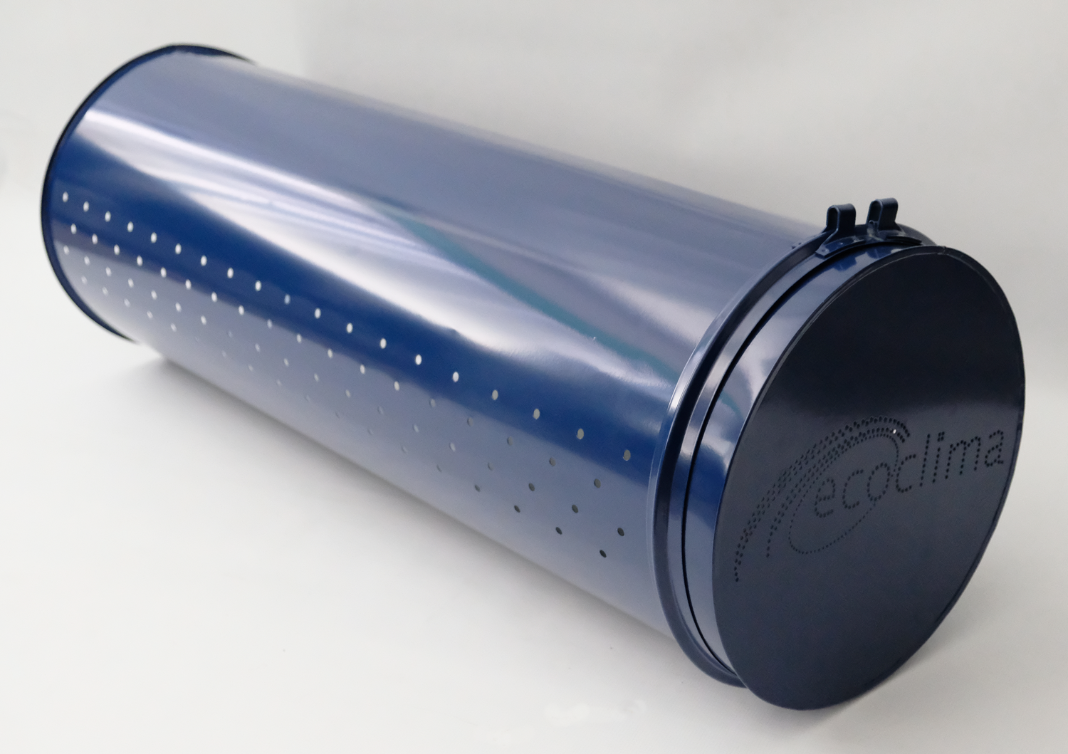
• Powder-coated sheet metal with customizable RAL color;
• In stainless steel 304, 316 or copper;
• Anti-condensation treatment applicable to the above surfaces;
• ETIM-O version: open ducts to reduce transport and assembly costs using the 10 seconds system;
System A
Central installation for spaces with a height from 2.5 m to 3.5 m. Suitable for habitable environments such as offices, shops.
H = 3 m;
L = 7 m;

System B
Central installation for environments with height from 3.5 m to 10 m. Suitable for both civil and industrial settings.
H = 9 m;
L = 18 m;

System C
Asymmetrical diffusion installation to create thermal barriers for glass surfaces, etc.
H = 9 m;
L = 18 m;

N.B. Diagrams simulated with residual speed 0.2 m at 1800 mm from the ground in a more conservative way than UNI 10339 and UNI EN 13779.
Pressure drop in circular duct
The limit of use of the metal induction tube is with speeds between approximately 3.5 and 7 m/s
| Ø | 200 | 300 | 400 | 500 | 600 | 700 | 800 | 900 | 1000 | 1100 |
| Air flow | Pa/m | |||||||||
| 500 | 10 | |||||||||
| 600 | 21 | |||||||||
| 700 | 32 | |||||||||
| 800 | 38 | |||||||||
| 1100 | 10 | |||||||||
| 1200 | 14 | |||||||||
| 1300 | 17 | |||||||||
| 1400 | 21 | |||||||||
| 1500 | 25 | |||||||||
| 1600 | 29 | |||||||||
| 1700 | 33 | |||||||||
| 1800 | 38 | 10 | ||||||||
| 1900 | 12 | |||||||||
| 2000 | 18 | |||||||||
| 2250 | 22 | |||||||||
| 2500 | 25 | |||||||||
| 2750 | 31 | |||||||||
| 3000 | 36 | 17 | ||||||||
| 3250 | 43 | 21 | ||||||||
| 3500 | 24 | |||||||||
| 3750 | 27 | 10 | ||||||||
| 4000 | 31 | 12 | ||||||||
| 4500 | 40 | 17 | ||||||||
| 5000 | 43 | 21 | 12 | |||||||
| 5500 | 25 | 15 | ||||||||
| 6000 | 29 | 17 | 10 | |||||||
| 6500 | 34 | 21 | 12 | |||||||
| 7000 | 39 | 24 | 15 | |||||||
| 8000 | 30 | 20 | 14 | |||||||
| 9000 | 36 | 24 | 18 | 10 | ||||||
| 10000 | 29 | 22 | 13 | |||||||
| 11000 | 34 | 25 | 17 | |||||||
| 12000 | 41 | 30 | 21 | 11 | ||||||
| 13000 | 33 | 23 | 13 | |||||||
| 14000 | 41 | 25 | 15 | |||||||
| 15000 | 30 | 18 | ||||||||
| 16000 | 34 | 20 | ||||||||
| 17000 | 37 | 22 | ||||||||
| 18000 | 43 | 24 | ||||||||
| 19000 | 27 | |||||||||
| 20000 | 29 | |||||||||
| 21000 | 33 | |||||||||
| 22000 | 34 | |||||||||
| 23000 | 40 | |||||||||
| 24000 | 43 | |||||||||
ETIM

Circular micro-perforated ducts in galvanized Z200 / painted / pre-painted / stainless steel 304 / stainless steel 316, as specified by the project manager, for air distribution in HVAC systems, ECOCLIMA brand, ETIM standard/O series.
The micro-perforations, with variable diameter and mesh, must create a high induction effect between supply and room air. Circular section ducts must be manufactured in 1 m / 1.5 m sections with 90° reinforced flange couplings. Perforations must be made with specific diameters and geometries based on the intended use of the serviced rooms.
The ECOCLIMA high-induction micro-perforated ducts are factory-calibrated to work without calibration dampers or air relief systems; the perforation pattern is specially calculated in diameter, quantity, and position for optimal air distribution.
Included in the price:
• Square to round transformation (if present)
• 90° bend (if present)
• End cap (if present)
• T-joint (if present)
Component connections must be made using screw-type clamp collars.

